Omron S8VK-X12024A-EIP

Satışla iletişime geçin

(0216) 540 59 91

Fiyat Teklifi İsteyin

Stok kodu: S8VK-X12024A-EIP Kategoriler: Etiketler: ,

Açıklama

Omron S8VK-X12024A-EIP Anahtarlamalı Güç Kaynağı

EtherNet/IP, Modbus TCP Uyumlu, Ekipmanın IoT’ye Bağlanması Yoluyla Sistem Düzeyini En Üst Düzeye Çıkarır

Ürün değişim zamanı, çıkış gerilimi, çıkış akımı ve daha fazlası ağ üzerinde bir araya getirilir ve bunların hepsi aynı anda yönetilebilir

  • Ürün durumu, gösterge ekranı kullanılarak yerinde kontrol edilebilir
  • -40 ile 70°C arasındaki ortam sıcaklıklarında çalışması mümkündür
  • %150 güç artırma fonksiyonu (240 ve 480 W)
  • Yan yana montaj mümkündür (55°C’ye kadar)
  • UL Sınıf 2 uygunluğu (90 W veya daha az)
  • EN/IEC 61558-2-16 ile uyumlu
  • Ortam koşullarına karşı daha iyi dayanım için silikon kaplı PCB’ler

Özellikler ve sipariş bilgisi

Ordering information

Note: For details on normal stock models, contact your nearest OMRON representative.

With Indication monitor

Power rating

Rated input voltage

Rated output voltage (DC)

Rated output current

Maximum boost current

Order code

90 W

100 to 240 VAC

(allowable range:
85 to 264 VAC,
90 to 350 VDC)

24 V

3.75 A

S8VK-X09024A-EIP

120 W

24 V

5 A

6 A

S8VK-X12024A-EIP

240 W

24 V

10 A

15 A

S8VK-X24024A-EIP

480 W

24 V

20 A

30 A

S8VK-X48024A-EIP

Without Indication monitor

Power rating

Rated input voltage

Rated output voltage (DC)

Rated output current

Maximum boost current

Order code

30 W

100 to 240 VAC

(allowable range:
85 to 264 VAC,
90 to 350 VDC)

5 V

5 A

6 A

S8VK-X03005-EIP

60 W

12 V

4.5 A

5.4 A

S8VK-X06012-EIP

24 V

2.5 A

3 A

S8VK-X06024-EIP

90 W

24 V

3.75 A

S8VK-X09024-EIP

120 W

24 V

5 A

6 A

S8VK-X12024-EIP

240 W

24 V

10 A

15 A

S8VK-X24024-EIP

480 W

24 V

20 A

30 A

S8VK-X48024-EIP

Accessories (Order Separately)

Mounting Brackets

Power rating

Mounting direction

Model number

30 W, 60 W

Front mounting

S82Y-VS10F

30 W, 60 W

Side mounting

S82Y-VS10S

240 W, 480 W

Front mounting

S82Y-VK10F

DIN Rail Mounting

Part name

Model number

Mounting Rail (Material: Aluminum)

PFP-100N

PFP-50N

PFP-100N2

End Plate

PFP-M

Recommended EtherNet/IP Communication Cables

Use an STP cable (shielded twisted pair cable) of Category 5 or above.

Part name

Manufacturer

Model number

Cable

Hitachi Metals, Ltd.

NETSTAR-C5E SA 0.5×4P

RJ45 connector

Panduit Corp.

MPS588-C

Recommended Industrial switching hubs

Shape

Name

Specification

Order code

Functions

No. of ports

Failure detection function

Industrial switching hub

Priority control (QoS): EtherNet/IP control

data priority

Failure detection: Broadcast storm/

LSI abnormality detection

10/100BASE-TX, Auto-Negotiation

3

No

W4S1-03B

5

No

W4S1-05B

5

Yes

W4S1-05C

Specifications

Power rating

30 W

60 W

Rated output voltage

5 V

12 V

24 V

Indication monitor

None

None

None

Efficiency

115 VAC input

78% typ.

85% typ.

85% typ.

230 VAC input

77% typ.

86% typ.

86% typ.

Input conditions

Voltage range

Single-phase, 85 to 264 VAC, 90 to 350 VDC, 265 to 300 VAC (1 second)

Frequency

50/60 Hz (47 to 450 Hz)

Input current

115 VAC input

0.53 A typ.

0.99 A typ.

1.1 A typ.

230 VAC input

0.32 A typ.

0.61 A typ.

0.67 A typ.

Power factor

Leakage current

115 VAC input

0.5 mA max.

230 VAC input

1 mA max.

Inrush current

115 VAC input

16 A typ.

230 VAC input

32 A typ.

Output characteristics

Rated output current

5 A

4.5 A

2.5 A

Rated output power

25 W

54 W

60 W

Maximum boost current

6 A

5.4 A

3 A

Voltage adjustment range

4.5 to 5.8V (with V. ADJ)

10.8 to 14 V (with V. ADJ)

21.6 to 28 V (with V. ADJ)

Ripple noise voltage

100 to 240 VAC input

130 mVp-p max.
at 20 MHz of bandwidth

120 mVp-p max.
at 20 MHz of bandwidth

110 mVp-p max.
at 20 MHz of bandwidth

Input variation influence

0.5% max.

Load variation influence

1.5% max.

Temperature variation influence

100 to 240 VAC input

0.05%/°C max.

Start up time

115 VAC input

1000 ms max.

1000 ms max.

1000 ms max.

230 VAC input

1000 ms max.

1000 ms max.

1000 ms max.

Hold time

115 VAC input

45 ms typ.

20 ms typ.

20 ms typ.

230 VAC input

240 ms typ.

120 ms typ.

110 ms typ.

Additional functions

Overload protection

Yes, automatic reset, intermittent operation type.

Overvoltage protection

Yes, 130% or higher of rated output voltage, power shut off (shut off the input voltage and turn on the input again).

Series operation

Yes (For up to two Power Supplies; external diodes required.)

Parallel operation

Yes (For up to two Power Supplies).

Output indicator

Yes (LED: Green)

Alarm indicator

Yes (LED: Red)

Indication monitor

Measurement and display details

Refer to datasheet.

Main display

None

Ethernet communication

Measurement and display details

Refer to datasheet.

Communication protocol

EtherNet/IP, Modbus TCP

Physical layer

100BASE-TX

Communication specifications

Refer to datasheet.

Insulation

Withstand voltage

3.0 kVAC for 1 min. (between all input terminals and output terminals, all EtherNet/IP ports), current cutoff 20 mA

2.0 kVAC for 1 min. (between all input terminals and PE terminals), current cutoff 20 mA

1.0 kVAC for 1 min. (between all output terminals and PE terminals), current cutoff 30 mA

0.5 kVAC for 1 min. (between all output terminals and all EtherNet/IP ports), current cutoff 30 mA

Insulation resistance

100 MΩ min. (between all output terminals and all input terminals/PE terminals) at 500 VDC

100 MΩ min. (between all EtherNet/IP ports and all input terminals) at 500 VDC

Environment

Ambient operating temperature

−40 to 70°C (Derating is required according to the temperature.) (with no condensation or icing)

Storage temperature

−40 to 85°C (with no condensation or icing)

Ambient operating humidity

95% max. (Storage humidity: 95% max.)

Vibration resistance

10 to 55 Hz, maximum 5 G, 0.42 mm half amplitude for 2 h each in X, Y, and Z directions

Shock resistance

150 m/s2, 3 times each in ±X, ±Y, ±Z directions

Reliability

MTBF

160,000 hrs typ.

Life expectancy

10 years min.

Construction

Weight

250 g max.

250 g max.

250 g max.

Cooling fan

No

Degree of protection

IP20 by EN/IEC 60529

Note: For further information please refer to datasheet.

Power rating

90 W

120 W

Rated output voltage

24 V

24 V

Indication monitor

Included

None

Included

None

Efficiency

115 VAC input

86% typ.

87% typ.

90% typ.

90% typ.

230 VAC input

87% typ.

88% typ.

92% typ.

92% typ.

Input conditions

Voltage range

Single-phase, 85 to 264 VAC, 90 to 350 VDC, 265 to 300 VAC (1 second)

Frequency

50/60 Hz (47 to 450 Hz)

50/60 Hz (47 to 63 Hz)

Input current

115 VAC input

1.7 A typ.

1.7 A typ.

1.2 A typ.

1.2 A typ.

230 VAC input

1.0 A typ.

1.0 A typ.

0.63 A typ.

0.63 A typ.

Power factor

0.9 min.

Leakage current

115 VAC input

0.5 mA max.

230 VAC input

1 mA max.

Inrush current

115 VAC input

16 A typ.

230 VAC input

32 A typ.

Output characteristics

Rated output current

3.75 A

5 A

Rated output power

90 W

120 W

Maximum boost current

6 A

Voltage adjustment range

23.0 to 24.1 V

21.6 to 28 V (with V. ADJ)

Ripple noise voltage

100 to 240 VAC input

300 mVp-p max. at 20 MHz of bandwidth

150 mVp-p max. at 20 MHz of bandwidth

Input variation influence

0.5% max.

Load variation influence

1.5% max.

Temperature variation influence

100 to 240 VAC input

0.05%/°C max.

Start up time

115 VAC input

1000 ms max.

1000 ms max.

230 VAC input

1000 ms max.

1000 ms max.

Hold time

115 VAC input

25 ms typ.

35 ms typ.

230 VAC input

130 ms typ.

35 ms typ.

Additional functions

Overload protection

Yes, automatic reset, intermittent operation type.

Overvoltage protection

Yes, 110% or higher of rated output voltage (90 W), 130% or higher of rated output voltage (120 W), power shut off (shut off the input voltage and turn on the input again.

Series operation

Yes (For up to two Power Supplies, external diodes are required.)

Parallel operation

Yes (For up to two Power Supplies).

Output indicator

Yes (LED: Green)

Alarm indicator

Yes (LED: Red)

Indication monitor

Measurement and display details

Refer to datasheet.

Main display

7-segment LED
(White)

None

7-segment LED
(White)

None

Ethernet communication

Measurement and display details

Refer to datasheet.

Communication protocol

EtherNet/IP, Modbus TCP

Physical layer

100BASE-TX

Communication specifications

Refer to datasheet.

Insulation

Withstand voltage

3.0 kVAC for 1 min. (between all input terminals and output terminals, all EtherNet/IP ports), current cutoff 20 mA

2.0 kVAC for 1 min. (between all input terminals and PE terminals), current cutoff 20 mA

1.0 kVAC for 1 min. (between all output terminals and PE terminals), current cutoff 30 mA

0.5 kVAC for 1 min. (between all output terminals and all EtherNet/IP ports), current cutoff 30 mA

Insulation resistance

100 MΩ min. (between all output terminals and all input terminals/PE terminals) at 500 VDC

100 MΩ min. (between all EtherNet/IP ports and all input terminals) at 500 VDC

Environment

Ambient operating temperature

−40 to 70°C (Derating is required according to the temperature.) (with no condensation or icing)

Storage temperature

−40 to 85°C (with no condensation or icing)

Ambient operating humidity

95% max. (Storage humidity: 95% max.)

Vibration resistance

10 to 55 Hz, maximum 5 G, 0.42 mm half amplitude for 2 h each in X, Y, and Z directions

Shock resistance

150 m/s2, 3 times each in ±X, ±Y, ±Z directions

Reliability

MTBF

110,000 hrs typ.

150,000 hrs typ.

110,000 hrs typ.

140,000 hrs typ.

Life expectancy

10 years min.

Construction

Weight

350 g max.

400 g max.

Cooling fan

No

Degree of protection

IP20 by EN/IEC 60529

Note: For further information please refer to datasheet.

Power rating

240 W

480 W

Rated output voltage

24 V

24 V

Indication monitor

Included

None

Included

None

Efficiency

115 VAC input

91% typ.

91% typ.

92% typ.

92% typ.

230 VAC input

93% typ.

93% typ.

94% typ.

94% typ.

Input conditions

Voltage range

Single-phase, 85 to 264 VAC, 90 to 350 VDC, 265 to 300 VAC (1 second)

Frequency

50/60 Hz (47 to 63 Hz)

50/60 Hz (47 to 63 Hz)

Input current

115 VAC input

2.4 A typ.

2.4 A typ.

4.6 A typ.

4.6 A typ.

230 VAC input

1.2 A typ.

1.2 A typ.

2.3 A typ.

2.3 A typ.

Power factor

0.9 min.

Leakage current

115 VAC input

0.5 mA max.

230 VAC input

1 mA max.

Inrush current

115 VAC input

16 A typ.

230 VAC input

32 A typ.

Output characteristics

Rated output current

10 A

20 A

Rated output power

240 W

480 W

Maximum boost current

15 A

30 A

Voltage adjustment range

21.6 to 28 V (with V. ADJ)

Ripple noise voltage

100 to 240 VAC input

140 mVp-p max. at 20 MHz of bandwidth

130 mVp-p max. at 20 MHz of bandwidth

Input variation influence

0.5% max.

Load variation influence

1.5% max.

Temperature variation influence

100 to 240 VAC input

0.05%/°C max.

Start up time

115 VAC input

1000 ms max.

1000 ms max.

230 VAC input

1000 ms max.

1000 ms max.

Hold time

115 VAC input

35 ms typ.

25 ms typ.

230 VAC input

35 ms typ.

25 ms typ.

Additional functions

Overload protection

Yes, automatic reset, intermittent operation type.

Overvoltage protection

Yes, 130% or higher of rated output voltage, power shut off (shut off the input voltage and turn on the input again).

Series operation

Yes (For up to two Power Supplies; external diodes required.)

Parallel operation

Yes (For up to two Power Supplies)

Output indicator

Yes (LED: Green)

Alarm indicator

Yes (LED: Red)

Indication monitor

Measurement and display details

Refer to datasheet.

Main display

7-segment LED (White)

None

7-segment LED (White)

None

Ethernet communication

Measurement and display details

Refer to datasheet.

Communication protocol

EtherNet/IP, Modbus TCP

Physical layer

100BASE-TX

Communication specifications

Refer to datasheet.

Insulation

Withstand voltage

3.0 kVAC for 1 min. (between all input terminals and output terminals, all EtherNet/IP ports),

2.0 kVAC for 1 min. (between all input terminals and PE terminals), current cutoff 20 mA

1.0 kVAC for 1 min. (between all output terminals and PE terminals), current cutoff 30 mA

0.5 kVAC for 1 min. (between all output terminals and all EtherNet/IP ports), current cutoff 30 mA

Insulation resistance

100 MΩ min. (between all output terminals and all input terminals/PE terminals) at 500 VDC

100 MΩ min. (between all EtherNet/IP ports and all input terminals) at 500 VDC

Environment

Ambient operating temperature

−40 to 70°C (Derating is required according to the temperature.) (with no condensation or icing)

Storage temperature

−40 to 85°C (with no condensation or icing)

Ambient operating humidity

95% max. (Storage humidity: 95% max.)

Vibration resistance

10 to 55 Hz, maximum 5 G, 0.42 mm half amplitude for 2 h each in X, Y, and Z directions

Shock resistance

150 m/s2, 3 times each in ±X, ±Y, ±Z directions

Reliability

MTBF

100,000 hrs typ.

130,000 hrs typ.

90,000 hrs typ.

120,000 hrs typ.

Life expectancy

10 years min.

Construction

Weight

700 g max.

1,100 g max.

Cooling fan

No

Degree of protection

IP20 by EN/IEC 60529

Note: For further information please refer to datasheet.

Standards

Standards

Harmonic current emissions

Conforms to EN 61000-3-2

EMI

Conducted emissions

Conforms to EN 61204-3 Class B, EN 55011 Class B

Radiated emissions

Conforms to EN 61204-3 Class B, EN 55011 Class B

EMS

Conforms to EN 61204-3 high severity levels

Safety standards

UL 508, ANSI/ISA 12.12.01 (Listing) (For 30 W, 60 W, and 90 W only Class 2 Output: Per UL 1310)

CSA C22.2 No. 107.1, CSA C22.2 No. 213 (cUL) (For 30 W, 60 W, and 90 W only Class 2 Output: Per CSA C22.2 No. 223)

UL 60950-1, UL 62368-1 (Recognition) OVC II ( 3000 m) Pol2 (For 30 W, 60 W, and 90 W only LPS)

CSA C22.2 No. 60950-1, No. 62368-1 (cUR) OVC II ( 3000 m) Pol2 (For 30 W, 60 W, and 90 W only LPS)

EN 50178 OVC III ( 2000 m) OVC II (2000 m < and 3000 m) Pol2

EN 60950-1, EN 62368-1 OVC II ( 3000 m) Pol2 (For 30 W, 60 W, and 90 W only LPS)

EAC (TR CU 004 / 2011, TR CU 020 / 2011)

RCM (EN61000-6-4)

Korea Radio Waves Act (Law No. 10564)

Conforms to PELV (EN/IEC 60204-1)

Conforms to EN/IEC 61558-2-16

SEMI

Conforms to F47-0706 (200 to 240 VAC input)

  • Note • EMI (radiated emissions) conform to Class B when this Power Supply is installed in a control panel.
  • • EN/IEC 61558-2-16
    The S8VK-X was designed based on EN/IEC 61558-2-16.
    Currently, IEC 61558-2-17 has been replaced by IEC 61558-2-16.
    When certification was received for EN/IEC 60204-1 (Machinery Safety), it was necessary to go through a control transformer to the control circuits. However, a control transformer is not always necessary for product that have been certified for the safety standard for OVCIII or for product that use a transformer that conforms to EN/IEC 61558-2-16.
  • • Safety Standards for a DC Input
    When DC is used, UL 60950-1, UL 62368-1, cUR (CSA 22.2 No. 60950-1), cUR (CSA C22.2 No. 62368-1), EN/IEC 60950-1, EN/IEC 62368-1, EN 50178 and EN/IEC 61558-2-16 are applicable to safety standards.
    Safety standard compliance is achievable by connecting a UL-certified fuse as specified below.
    Select an external fuse that satisfies the following conditions:
    S8VK-X03005-EIP, S8VK-X06012-EIP, S8VK-X06024-EIP (350 VDC or more, 6 A)
    S8VK-X09024⬜-EIP, S8VK-X12024⬜-EIP, S8VK-X24024⬜-EIP (350 VDC or more, 8 A)
    S8VK-X48024⬜-EIP (350 VDC or more, 12 A)
  • • To comply with PELV output requirements for EN/IEC 60204-1, ground the negative side of the output (-V) to a protective earth (PE).

Ek üniteler

S8T-DCBU-02


undefinedAnlık güç kesintileri yüzünden ekipmanın durmasını, veri kaybını ve karşılaşılabilecek diğer problemleri engeller. Tek bir S8TS-DCBU-02 buffer bloğu 2,5A’lik 500ms’lik back-up zamanı sağlar. 24VDC’lik herhangi bir güç kaynağına bağlanabilir.

S8M


undefined
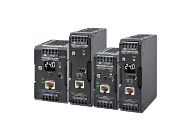
Maksimum dalgalanma kanal başına ( ayarlanabilir ) 3.8A olan S8M ile makinanız doğrudan UL Sınıf 2’ye uyumlu olacaktır. Bu ünite 4 devreye kadar kontrol eder. Buna ek olarak açılış/kapanış sıralı kontrolü, ekran ve gerilim, çıkış akımı, çalışma zamanı ve aşırı sıcaklık gibi alarm çıkış fonksiyonları ve harici reset’e sahip olursunuz. Bu fonksiyonlar ön yüzdeki butonlardan ya da ücretsiz olarak temin edilen destek yazılım gereci ile ayarlanabilir. Bu ayarlar korunabilir.

S8VK-R


undefined
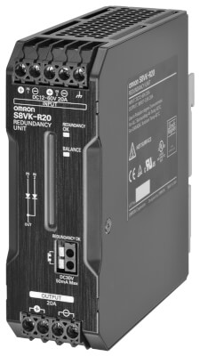
Anahtarlamalı güç kaynaklarıyla kullanıldığında, S8VK-R mutlak güvenilirlik ve hiç aksamaya neden olmayan kritik uygulamalar için yedek bir sistem sağlar.

S8V-NF


DIN Ray Montaj Tipi Kontrol Panoları için İdealdir, Yerden Tasarruf Sağlayan İnce Tasarıma Sahiptir, Emniyetli ve Kolay Kablolama için Push-In Bağlantılar

Dosya indirme

Broşürler


Cihaz tanımı dosyaları (ZIP)


Veri Sayfası


Kılavuzlar


Yazılım (ZIP)