Açıklama
Omron G7SA-3A3B; Zorlamalı kontaklı röleler
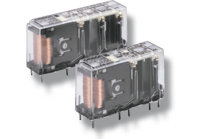
Zorlamalı kontaklı ince Omron G7SA-3A3B röle ailesi dört veya altı kutuplu olarak çeşitli kontak kombinasyonlarında mevcuttur ve güçlendirilmiş yalıtım sağlamaktadır. Terminaller kolay PCB yerleşimi için düzenlenmiştir Doğrudan bir PCB’ye lehimlenebilir veya P7SA soketlerle kullanılabilir.
- Zorlamalı kontaklar
- EN 50205’ye uygundur
- 240 VAC’de 6A ve dirençli yükler için 24 VDC’de 6 A
- Girişler, çıkışlar ve kutuplar arasında güçlendirilmiş yalıtım
- 4 ve 6 kutuplu röleler mevcuttur
- Push-in teknolojisine sahip uygun soketler
Diğer emniyet kontrolörleri için tıklayınız.
Ürün broşürü
Özellikler ve sipariş bilgisi
Relays with forcibly guided contacts
|
Type
|
Sealing
|
Poles
|
Contacts
|
Rated voltage
|
Order code
|
|
Standard
|
Flux-tight
|
4 poles
|
3PST-NO, SPST-NC
|
24 VDC
|
G7SA-3A1B
|
|
DPST-NO, DPST-NC
|
G7SA-2A2B
|
|
6 poles
|
5PST-NO, SPST-NC
|
G7SA-5A1B
|
|
4PST-NO, DPST-NC
|
G7SA-4A2B
|
|
3PST-NO, 3PST-NC
|
G7SA-3A3B
|
Sockets
|
Mounting
|
Terminal type
|
LED indicator
|
Poles
|
Coil rated voltage
|
Order code
|
|
Front-
mounting
|
Push-In Plus terminals
|
Yes
|
4 poles
|
24 VDC
|
P7SA-10F-ND-PU
|
|
6 poles
|
P7SA-14F-ND-PU
|
|
Screw terminals
|
Yes
|
4 poles
|
P7SA-10F-ND
|
|
6 poles
|
P7SA-14F-ND
|
|
No
|
4 poles
|
−
|
P7SA-10F
|
|
6 poles
|
P7SA-14F
|
|
Back-
mounting
|
PCB terminals
|
No
|
4 poles
|
−
|
P7SA-10P
|
|
6 poles
|
P7SA-14P
|
Specifications
Coil
|
Rated voltage
|
Rated current
|
Coil resistance
|
Must-operate voltage
|
Must-release voltage
|
Max. voltage
|
Power consumption
|
|
24 VDC
|
4 poles: 15 mA
6 poles: 20.8 mA
|
4 poles: 1,600 Ω
6 poles: 1,152 Ω
|
75% max. (V)
|
10% min. (V)
|
110% (V)
|
4 poles: Approx. 360 mW
6 poles: Approx. 500 mW
|
Note: Refer to datasheet for details
Contacts
|
Load
|
Resistive load (cos φ = 1)
|
|
Rated load
|
6 A at 250 VAC, 6 A at 30 VDC
|
|
Rated carry current
|
6 A
|
|
Max. switching voltage
|
250 VAC, 125 VDC
|
|
Max. switching current
|
6 A
|
|
Max. switching capacity (reference value)
|
1,500 VA, 180 W
|
Relays with forcibly guided contacts
|
Contact resistance
|
100 mΩ max. (The contact resistance was measured with 1 A at 5 VDC using the voltage-drop method.)
|
|
Operating time
|
20 ms max.
|
|
Response time
|
10 ms max.
(The response time is the time it takes for the normally open contacts to open after the coil voltage is turned OFF.)
|
|
Release time
|
20 ms max.
|
|
Insulation resistance
|
100 MΩ min. (at 500 VDC) (The insulation resistance was measured with a 500 VDC megger at the same places that the dielectric strength was
measured.)
|
|
Dielectric strength
|
Between coil contacts/different poles: 4,000 VAC, 50/60 Hz for 1 min
(2,500 VAC between poles 3-4 in 4-pole Relays or poles 3-5, 4-6, and 5-6 in 6-pole Relays.)
Between contacts of same polarity: 1,500 VAC, 50/60 Hz for 1 min
|
|
Durability
|
Mechanical
|
10,000,000 operations min. (at approx. 36,000 operations/hr)
|
|
Electrical
|
100,000 operations min. (at the rated load and approx. 1,800 operations/hr)
|
|
Min. permissible load
|
5 VDC, 1 mA (reference value)
|
|
Ambient temperature
|
Operating: −40 to 85°C (with no icing or condensation)
|
|
Ambient humidity
|
Operating: 35 to 85%
|
|
Approved standards
|
EN61810-1 (IEC61810-1), EN50205, UL508, CSA22.2 No. 14
|
Note: The values listed above are initial values.
Please check Omron in the Internet for updated information on product reliability data and the SISTEMA libraries: http://industrial.omron.eu/safety