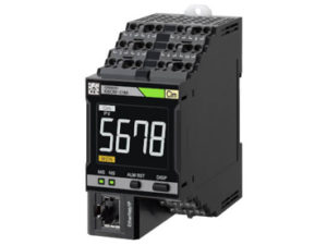
K6CM-ISM

Contact sales

+90 216 540 59 91

Request a Price Quote

Description

K6CM-ISM

Motor Condition Monitoring Device

K6CM-ISM; Quantifying the status of a three-phase induction motor and pump. The alarm output threshold default is set. You can customize the value according to the site. As for comprehensive current diagnosis, the degradation can be detected comprehensively by combining each motor part and the load side. The insulation resistance of the threephase induction motor and pump can be measured with current flowing (the secondary side leakage current of the inverter can also be detected).

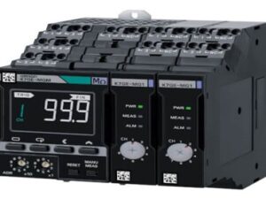
Since the condition of the motor can be displayed in numeric values on the LCD, the motor condition can be checked without a dedicated tool.

  • The alarm output settings can be made according to the device, with reference to the threshold value that has already been set by default.
  • Depending on the threshold value setting for alarm output, the condition of the motor can be displayed on an alarm bar in three colors; Green (normal), Orange (warning), and Red (critical).
  • Equipped with a transistor output that externally outputs the status of the motor and error states of the K6CM main unit.
  • Monitoring can be performed easily on the PC by EtherNet/IP communication and a dedicated tool.
  • The numeric values of vibrations, temperature, insulation resistance, and current can be monitored by the same dedicated tool.
  • The trend of the motor condition can be monitored by a dedicated tool, and thus indications of a degradation can be monitored.
  • Clamp-type CT/ZCT that supports easy post installation. With a clamp-type CT/ZCT, the device can be installed without changing or removing the existing wiring, which makes post-installation easy.
  • Comes with the self-diagnosis function of the main unit internal circuit and analog sensing circuit.
  • Push-in Plus Terminal Technology reduces wiring work (double-insertion holes for crossover wiring).
  • UL listed for easy shipping to North America (ZCT (IRT) is UL recognized).

Datasheet
Click for other condition monitoring devices

Specifications & ordering info

Ordering information

List of models


Monitoring type

Power supply voltage

Order code

Vibration & temperature type

100 to 240 VAC

K6CM-VBMA-EIP

24 VAC/VDC

K6CM-VBMD-EIP

Insulation resistance type

100 to 240 VAC

K6CM-ISMA-EIP

24 VAC/VDC

K6CM-ISMD-EIP

Comprehensive current diagnosis type

100 to 240 VAC

K6CM-CIMA-EIP

24 VAC/VDC

K6CM-CIMD-EIP

Input part

Vibration & temperature sensor (Order separately)


Appearance
(pre-amplifier)

Appearance
(head)

Attachment part

Applicable relay

Order code

M6 screw

K6CM-VBM

K6CM-VBS1

Note: The vibration and temperature sensor consists of a sensor head and a pre-amplifier.
A magnet is provided for the easy attachment of the vibration and temperature sensor.

ZCT (IRT) (Order separately)


Rated voltage

Through hole dia. (mm)

Applicable Relay

Order code

200 to 480 VAC

52 dia.

K6CM-ISM

K6CM-ISZBI52

Note: CT (IRT) is the abbreviation for Zero Current Transfer (Insulation Resistance Transfer).
A cable for connection is provided with the ZCT (IRT).

CT (Order separately)


Rated primary-side current

Applicable Relay

Order code

5 A

K6CM-CIM

K6CM-CICB005

25 A

K6CM-CICB025

100 A

K6CM-CICB100

200 A

K6CM-CICB200

400 A

K6CM-CICB400

600 A

K6CM-CICB600

Note: A cable for connection is provided with the CT. Select a CT that sets the current of the applicable motor within the measurement range.

EtherNet/IP communication cable recommended parts

Use a Category 5 or higher STP cable (shielded twisted pair cable).


Part name

Manufacturer

Order code

Cable

Hitachi Metals, Ltd.

NETSTAR-C5E SA 0.5 × 4P

2


2.

It is recommended to use the cable and connector in combination described above.

RJ45 connector

Panduit Corporation

MPS588-C

1


2.

It is recommended to use the cable and connector in combination described above.

Industrial switching hub (recommended parts)


Appearance

Product name

Specifications

Order code

Function

No. of ports

Failure detection function

Industrial switching hub

Priority control (QoS): EtherNet/IP control data priority

Failure detection: Broadcast storm /

LSI failure detection

10/100BASE-TX, Auto-Negotiation

3

No

W4S1-03B

5

No

W4S1-05B

5


Yes

W4S1-05C

Specifications

List of models

Ratings


Power Supply

Power supply voltage

K6CM-
⬜⬜

MA: 100 to 240 VAC, 50/60 Hz

K6CM-
⬜⬜

MD: 24 VAC, 50/60 Hz, 24 VDC

Allowable operating voltage range

85% to 110% of power supply voltage

Power supply frequency range

45 to 65 Hz

Power consumption

K6CM-VBM

24 VAC/24 VDC: 3.8 VA/2.1 W max.

100 to 240 VAC: 7.1 VA max.

K6CM-ISM

24 VAC/24 VDC: 3.7 VA/2.0 W max.

100 to 240 VAC: 6.2 VA

K6CM-CIM

24 VAC/24 VDC: 3.1 VA/1.6 W max.

100 to 240 VAC: 6.0 VA max.

Input

Vibrations
(vibration sensor)

Detection frequency

10 Hz to 10 kHz

Max. operating acceleration

10 G

Insulation resistance (ZCT (IRT))

Rated input voltage

(Line voltage) 200 to 480 VAC, 50 Hz/60 Hz

Rated path current

300 AAC

Current, comprehensive current diagnosis (CT)

Rated input current

5 A, 25 A, 100 A, 200 A, 400 A, 600 A

Applicable motor type

Three-phase induction motor

Outputs

Output relays

Transistor output (N.C. contact)

Output relays

3-point

Output rating

Rated voltage: 24 VDC

Max. current: 50 mA, DC

Ambient operating temperature

−10 to +55°C (with no condensation or icing)

Storage temperature

−20 to +65°C (with no condensation or icing)

Ambient operating humidity

25% to 85% RH (with no condensation)

Storage humidity

25% to 85% RH (with no condensation)

Case color

Black

Case material

Polycarbonate UL94-V0

Altitude

2,000 m max.

Applicable wires

Stranded wires, solid wires, or ferrules

Applicable wire size

0.25 to 1.5 mm2 (AWG24 to 16)

Wire insertion force

8 N max. (AWG20)

Screwdriver insertion force

15 N max.

Wire stripping length

8 mm

Recommended flat-blade screwdriver

XW4Z-00B (Omron)

Current capacity

10 A (per pole)

Number of insertions

50 times

Weight

Approx. 200 g

Mounting

Mounts to DIN Track

screw mounting

Dimensions

45 (W) × 90 (H) × 90 (D) mm

Setting method

Communication settings from a dedicated tool via EtherNet/IP

Other functions

Display value selection, self-diagnosis error output, setting value initialization, operation integration

Accessories

Operation manual, CD-ROM (Motor condition monitoring Tool)

Characteristics


Item

K6CM-VB

K6CM-IS

K6CM-CI

Measurement range

Acceleration: Up to 9.99 G,
Velocity: Up to 45 mm/s,
Motor temperature: 0 to 80°C,
Differential temperature: 0 to 80°C

Insulation resistance: 0.000 M to 1.000 MΩ,

Leakage current: 0.00 mA to 200.0 mA

Current

Rating 5 A: 1.00 to 5.00 A

Rating 25 A: 5.0 to 25.0 A

Rating 100 A: 20.0 to 100.0 A

Rating 200 A: 40.0 to 200.0 A

Rating 400 A: 80.0 to 400.0 A

Rating 600 A: 120.0 to 600.0 A

Degradation level: 0 to 999

Measurement absolute accuracy

Acceleration

±3 dB±2 digit

Temperature

Motor temperature: ±3°C±2 digit (±6°F±1 digit)

Temperature Gap: ±6°C±2 digit (±12°F±1 digit)

Insulation resistance

±35% rdg±2 digit (when the insulation resistance is 0.2 MΩ max.), when a 200-V/7.5-kW max. motor is used

3


3.

For details, refer to the technical data on page 16.

±35% rdg±2 digit (when the insulation resistance is 0.4 MΩ max.), when a 400-V/7.5-kW max. motor is used

1


3.

For details, refer to the technical data on page 16.

Current

±1.0% FS±1 digit (excluding CT variation)

Sampling cycle

Acceleration: 50 ms, Velocity: 0.5 s,
Temperature: 0.5 s

Normal mode: 10 s,
Inverter special measurement mode: 60 s

Comprehensive current diagnosis: 5 s,
Current: 5 s

Moving average frequency

1, 2, 4, 8, 16, 32 times

External trigger

External contact input specification

Short-circuit: Residual voltage 1.5 V max.

Open: Leakage current 0.1 mA max.

Short-circuit: Residual voltage 1.5 V max.

Open: Leakage current 0.1 mA max.

Current during short-circuiting

Approx. 7 mA

Approx. 7 mA

Transistor output

Contact configuration: NPN open collector (normal close)

Rated voltage: 24 VDC (maximum voltage: 26.4 VDC)

Max. current: 50 mA, DC

Alarm

Parameters that can be output

Acceleration, Velocity, motor temperature, Temperature Gap

Insulation resistance

Degradation level, current

Expression method

Transistor output, alarm bar

Setting value

Same as the measurement range

Hysteresis

10% width of setting value

Reset method

Manual reset/automatic reset (switchable)


Manual return method: Press the ALMRST button

LCD display

7-Segment digital display and single-shot display

Font height 14 mm

Applicable standards

Conforming standards

EN61010-2-030

Installation environment: Pollution degree 2, overvoltage category II, measurement category II

EMC

EN61326-1(EMI: Class A EMS: Industrial Location)

Acceleration ± 0.1G, Velocity ±2.25mm/s, Temperature ± 6°C, insulation resistance ± 35% rdg, current ± 10% F.S.

Safety standards

UL61010-2-030 (listing)

Korean Radio Waves Act (Act 10564)

RCM

EAC

Insulation resistance

20 MΩ min.

Between all external terminals and the case

Between all power supply terminals and all other terminals

Between all sensor connection terminals and trigger input terminal + output terminal + all EtherNet/IP ports

Dielectric strength

2,000 VAC for 1 minute

Between all external terminals and the case

Between all power supply terminals and all other terminals

Between all sensor connection terminals and trigger input terminal + output terminal + all EtherNet/IP ports

Vibration resistance

Vibration frequency 10 to 55 Hz, slice amplitude 0.35 mm in each of X, Y, Z directions 5 minute × 10

Shock resistance

100 m/s2, 3 times each in 6 directions along 3 axes

Degree of protection

IP20

LED display

Alarm bar

Red/Orange/Green

MS, NS

4


4.

MS: Product status display, NS: Network status display.


Red/Green

Ethernet communication

Communication protocol

EtherNet/IP

Physical layer

100BASE-TX

Transmission distance

100 m (Distance between hub and node)

Input part

Vibration & temperature sensor

Ratings


Item

K6CM-VBS1

Power supply voltage

Supplied from K6CM-VBM

Sensor head

Max. acceleration

10 G

Ambient operating temperature

Pre-amplifier: −10 to +55°C (with no condensation or icing)

Sensor head: −10 to +80°C (with no condensation or icing)

Storage temperature

Pre-amplifier: −20 to +65°C (with no condensation or icing)

Sensor head: −20 to +90°C (with no condensation or icing)

Ambient operating humidity

25% to 85% RH (with no condensation)

Storage humidity

25% to 85% RH (with no condensation)

Altitude

2,000 m max.

Case color

Pre-amplifier: Black

Sensor head: Silver

Case material

Pre-amplifier: Polycarbonate UL94-V0

Sensor head: Aluminum alloy (ADC12) / Zinc die casting (ZDC2) (the threaded part is Steel (S45C))

Weight

Pre-amplifier: Approx. 210 g (including cables)

Sensor head: Approx. 40 g (including cables)

Mounting

Pre-amplifier: DIN rail mounting, screw mounting

Sensor head: Screw mounting

Between pre-amplifier and sensor head: Connector connection (smart click connector)

Wire length

Between pre-amplifier and sensor head: 2.6 m+0.3 m (cannot be extended)

Between pre-amplifier and main unit: 1 m Can be extended up to a maximum length of 100 m

Characteristics


Item

K6CM-VBS1

Measurement range

Specified in main unit “Characteristics”

Applicable standards

Conforming standards

EN 61010-2-030

Installation environment: Pollution degree 2, overvoltage category II, measurement category II

EMC

EN 61326-1 (EMI: Class A EMS: Industrial Location)

Safety standards

UL 61010-2-030 (listing)

RCM

EAC

Insulation resistance

20 MΩ min.

Dielectric strength

500 VAC for one minute

Vibration resistance

Pre-amplifier

Vibration frequency 10 to 55 Hz, slice amplitude 0.35 mm in each of X, Y, Z directions 5 minute × 10 sweeps

Sensor head

Vibration frequency 10 to 55 Hz, slice amplitude 0.35 mm in each of X, Y, Z directions 5 minute × 10 sweeps

Shock resistance

Pre-amplifier

100 m/s2, 3 times each in 6 directions along 3 axes

Sensor head

100 m/s2, 3 times each in 6 directions along 3 axes

Degree of protection

Pre-amplifier

IP20 (excluding the sensor-side cable)

Sensor head

Conforming to IP67G (JIS C 0920 : 2003, Appendix 1)

LED display

Pre-amplifier PWR: Green, ERR: Red, COM: Orange

ZCT (IRT)


Item

K6CM-ISZBI52

Construction

Indoor split type

Rated path current

300 A

Through hole dia.

52 mm dia.

Rated voltage

200 to 480 VAC, 50 Hz/60 Hz three phase

Measurement range

Specified in main unit “Characteristics”

Measurement accuracy

Specified in main unit “Characteristics”

Voltage input terminal

3-terminal lead wire, Length: 1m (pre-wired cable)

Output terminal

4-terminal lead wire, Length: 1m (pre-wired cable) Available wire length 100 m max.

Applicable standards

Conforming standards

EN 61010-2-030

Installation environment: Pollution degree 2, overvoltage category II, measurement category II

EMC

EN 61326-1 (EMI: Class A EMS: Industrial Location)

Safety standards

UL 61010-2-030 (Recognition) + CSA C22.2 No. 61010-2-030

RCM

EAC

Insulation resistance

Between Mounting bracket – Secondary winding: 100 MΩ min.

Dielectric strength

Between Mounting bracket – Secondary winding: 2000 VAC, 1 minute

Ambient operating temperature

−10 to +55°C (with no icing)

Ambient operating humidity

25 to 85% RH

Weight

Approx. 2.3 kg (including cables)

CT


Item

K6CM-CICB005

K6CM-CICB025

K6CM-CICB100

K6CM-CICB200

K6CM-CICB400

K6CM-CICB600

Construction

Indoor split type

Primary-side rated current

5 A

25 A

100 A

200 A

400 A

600 A

Measurement range

5


5.

Select a CT that brings the current of the applicable motor into the measurement range.

1 to 5 A

5 to 25 A

20 to 100 A

40 to 200 A

80 to 400 A

120 to 600 A

Secondary-side rated current

Dedicated current

Secondary winding

3000 turns

6000 turns

9000 turns

Applicable frequency

10 Hz to 5 kHz

Insulation resistance

Between output terminal and case: 50 MΩ min.

Dielectric strength

Between output terminal and case: 2,000 VAC, 1 minute

Protective element

7.5 V clamp element

Permissible attachment/removal frequency

100 times

Attachable wire diameter

6.
When using a flat wire, be sure to refer to the external dimensions drawing of the CT.

7.9 mm dia. max.

9.5 mm dia. max.

14.5 mm dia. max.

24.0 mm dia. max.

35.5 mm dia. max.

Operating temperature/humidity range

−20 to +60°C, 85% max. (with no condensation)

Storage temperature/humidity range

−30 to +65°C, 85% max. (with no condensation)

Supplied cable length

2.9 m (pre-wired cable)

Supplied cable terminal

Main unit side

Ferrule terminal

CT side

Round terminal

Motor condition monitoring Tool (Software included with main unit)


Item

Specification

Project

Number of files that can be created

No limit

Import

Supported format

CSV data format

Measurement interval that can be imported

1 second to 99999 second (one-second step)

Number that can be registered in one project

Number of motors (device groups)

10

Number of devices per motor (device group)

3

7


7.

One vibration and temperature type, one insulation resistance type, and one current comprehensive diagnosis type can be set for one motor.

Graphic display

Type of graph

Line graph

Display period

1 hour, 1 day, 1 month, 3 months, 6 months,
1 year, 2 years, 5 years, 10 years, 20 years


Downloads

Brochures


Datasheet