F3S-TGR-S_A/-S_D

Contact sales

+90 216 540 59 91

Request a Price Quote

Description

F3S-TGR-S_A/-S_D

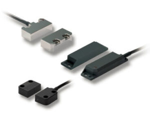
Standalone non-contact door switch

F3S-TGR-S_A/-S_D; Standalone non-contact switches support applications like guarding doors or position monitoring in machines. They are using the proven Omron non-contact technology allowing to cover mechanical tolerances and vibrations.

  • Models with single or dual actuator available
  • Based on hall technology
  • Connect up to 20 switches in series
  • LED for easy diagnosis
  • Operates behind stainless steel fittings
  • Non-contact – no abrasion – no particles
  • Compensation of mechanical tolerances
  • Suitable for high pressure cleaning, CIP and SIP processes due IP69K (pre-wired types)
  • Conforms to safety categories up to PLe acc. EN ISO 13849-1

Specifications & ordering info

Switches

Polyester housing

Type

Cable connection

Order code

Single actuator sensing

5 m pre-wired

F3S-TGR-SPSA-05

10 m pre-wired

F3S-TGR-SPSA-10

M12, 8-pin

F3S-TGR-SPSA-M1J8

Dual actuator sensing

5 m pre-wired

F3S-TGR-SPSD-05

10 m pre-wired

F3S-TGR-SPSD-10

M12, 8-pin

F3S-TGR-SPSD-M1J8

Stainless steel housing

Type

Cable connection

Order code

Single actuator sensing

5 m pre-wired

F3S-TGR-SMSA-05

10 m pre-wired

F3S-TGR-SMSA-10

M12, 8-pin

F3S-TGR-SMSA-M1J8

Dual actuator sensing

5 m pre-wired

F3S-TGR-SMSD-05

10 m pre-wired

F3S-TGR-SMSD-10

M12, 8-pin

F3S-TGR-SMSD-M1J8

Accessories

Order code

Cables 8-pin

2 m

Y92E-M12PURSH8S2M-L

5 m

Y92E-M12PURSH8S5M-L

10 m

Y92E-M12PURSH8S10M-L

25 m

Y92E-M12PURSH8S25M-L

Actuators (only for master coded types)

for F3S-TGR-SPSA and -SPSD

F39-TGR-SPS-A

for F3S-TGR-SMSA and -SMSD

F39-TGR-SMS-A

Mounting screws

Set of Torx safety screws (M4, 4 × 30 mm, 4 × 20 mm, 4 × 10 mm; incl. washers and Torx bit)

F39-TGR-N-SCREWS

Specifications

Mechanical data

Item

Model

Polyester Sensor

Stainless steel sensor

Indicator

Green LED: Indication of safety circuits closed (Guard closed, actuator present, feedback circuit checked)

Yellow LED: Indication of safety circuits open (Actuator removed)

Operating distance

OFF  ON (Sao)

10 mm Close

ON  OFF (Sar)

15 mm Open

Actuator approach speed

Min.

4 mm/s

Max.

1,000 mm/s

Operating temperature

-25 to 45°C

Enclosure protection

Flying lead

IP69K

M12 connector

IP67

Material cable

Flying lead

PVC, Ø 6 mm o.d.

M12 connector

250 mm, PVC, Ø 6 mm o.d.

Material housing

UL approved Polyester

Stainless steel 316

Electrical data

Item

Model

Polyester sensor

Stainless steel sensor

Sensing technology

Hall

Serial connection

up to 20 switches

Power supply

24 VDC±10%

Power consumption

Max.

0.1 A

Switching current

Min.

10 mA, 5 VDC

Rated loads

Safety outputs

Max.

3 A, 250 VAC/3A, 24 VDC

Auxiliary output

Max.

0.2 A, 24 VDC

Approved standards

EN standards certified by TÜV Rheinland

EN ISO13849-1

EN 62061

EN ISO 14119

EN 60204-1

EN/IEC 60947-5-3

UL 508, CSA C22.2

BS 5304

EN 1088-1 conformance

Wiring example (serial connection with manual restart)

(up to PLe acc. EN ISO 13849-1)

Safety Circuit 1 (Black/White) utilises internally checked force guided relay contacts and is connected in series with the corresponding Safety Circuit 2 (Yellow/Green) of the next switch. Allows minimal wiring and higher current switching to K1 and K2 contactors.

A manual start and contactor feedback check is achieved by connecting K1(Aux) and K2(Aux) feedback contacts and momentary start button through the orange and brown feedback check.

Downloads

Catalogue


Datasheet