|
Codes and Standards
|
IEC 60947-5-3:2013, EN 60947-5-1:2004 + AC:2005 + A1:2009,
EN 60947-1:2007 + A1:2011, EN ISO 13849-1:2008 + AC:2009,
EN 62061:2005 + AC:2010 + A1:2013, ISO 14119:2013, UL508
|
|
Safety Classification and Reliability Data
|
Minimum Switched Current
|
10 VDC 1 mA
|
|
Dielectric Withstand
|
250 VAC
|
|
Insulation Resistance
|
100 M Ω
|
|
Shock Resistance
|
11 ms 30G
|
|
Vibration Resistance
|
10 to 55 Hz, 1 mm amplitude
|
|
Switching Distance
|
S ao 1 mm Close; S ar 10 mm Open
|
|
Misalignment
|
Between switch and actuator, 2 mm in any direction
|
|
Switching Frequency
|
1.0 Hz maximum
|
|
Response Time (On –> Off)
|
10 ms max.
|
|
Operating Time (Off –> On)
|
150 ms
|
|
Approach Speed
|
200 to 1000 mm/s
|
|
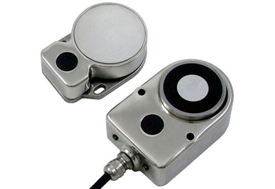
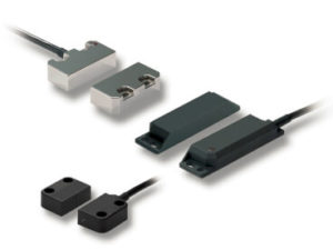
Body Material
|
D40ML-P_: Plastic
D40ML-M_: Diecast Metal
D40ML-SS_: 316 Stainless Steel
Actuator Seal: Silicone
Encapsulation: High Temperature Epoxy
|
|
Operating Temperature Range
|
–25 to 40°C
|
|
Ambient Operating Humidity
|
up to 90% at 25 ~ 40°C
|
|
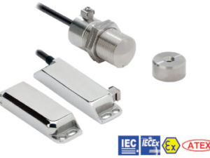
Enclosure Protection
|
IP67 (Plastic or Diecast Metal)
IP69K (Stainless steel versions with flying leads)
|
|
Cable Type
|
PVC 8 core, 6 mm outer diameter
|
|
Mounting Bolts
|
2 × M5 Tightening torque 1.0 Nm
|
|
Mounting Position
|
Any
|
|
Power Supply
|
24 VDC ±10% (selv / pelv)
|
|
Power Consumption
|
Unlocked: 50 mA max.
Locked:
- Medium Duty 325 mA max.
- Heavy Duty 500 mA max.
|
|
Holding Force
|
Medium Duty
- Stainless Steel: F1 max (typical) 600 N, F zh
450 N
- Plastic and Diecast: F1 max (typical) 900 N, F zh 675 N
Heavy Duty
- Stainless Steel: F1 max (typical) 950 N, F zh 700 N
- Plastic and Diecast: F1 max (typical) 1500 N, F zh 1150 N
|
|
Max. Switched Current (Outputs)
|
200 mA (min. internal resistance 8.5 Ohms)
|
|
Auxiliary Signal
|
+24 VDC (Door Open)
|
|
Characteristic Data according to EN ISO13849-1
|
PLe: If both channels are used in combination with a SIL3/PLe control device
Category: Cat. 4
MTTFd: 1100a
Diagnostic Coverage DC: 99% (high)
Number of operating days per year: d op = 365d
Number of operating hours per day: h op = 24h
B10d: Not mechanical parts implemented
|
|
Characteristic Data according to IEC62061
(used as a sub system)
|
Safety Integrity Level: SIL3
PFH (1/h): 4.77E-10 Corresponds to 4.8% of SIL3
PFD: 4.18E-05 Corresponds to 4.2% of SIL3
Proof Test Interval T 1 : 20a
|
|
Information with regard to UL508
|
Use LVLC or Class 2 supply. Type 1 enclosure.
|
|
Risk Time in accordance with EN 60947-5-3
|
150 ms (switching off delay at removal of actuator)
|